


News: LEDs
18 March 2021
Cool thermoelectric/LED assembly
Huazhong University of Science and Technology and Wuhan Polytechnic University in China have developed a blue light-emitting diode (LED) on thermoelectric cooler (TEC) assembly process with a view to improving high-power performance [Shuang Li et al, IEEE Transactions on Electron Devices, published online 10 March 2021]. The LED chips were directly solder-attached to the cold-side substrate of the TECs, avoiding the use of thermally resistive organic adhesives.
LEDs suffer from thermal degradation at high input power due to Joule and radiant heating effects. Apart from reduced light output power, thermal issues can reduce reliability and lifetimes of devices, along with shifting the emission wavelength. Emission intensity can fall by 1% with a 1°C increase in temperature. The researchers comment: “The heat dissipation problem is one of the technical choke points to the development of high-power LEDs.”
Thermal management through passive heat dissipation can be inadequate in such circumstances, and various active cooling methods might help, using fans, liquid flow, etc. Solid-state TECs use the Peltier effect to pump heat away from devices. Such devices use semiconductor materials and a bias to achieve cooling. The team sees TECs as an attractive option “due to its clean, no noise, high reliability, and cost-effective advantages”.
Previous attempts to combine TECs with LEDs have used organic adhesives, which are relatively resistive to heat flow. By contrast the new assemblies used direct solder attachment to the TEC cold-side substrate, improving the potential cooling effect. A further advantage to avoiding organic adhesives is that such materials suffer thermal aging effects, impacting reliability.
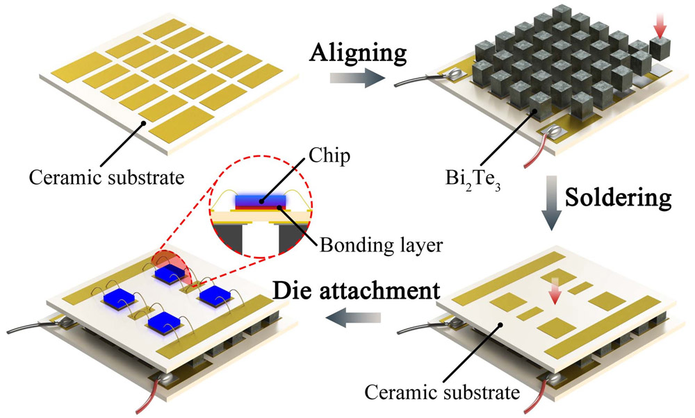
Figure 1: Fabrication process of chip-on-TEC for high-power LED packaging.
The researchers used aluminium oxide (Al2O3) ceramic substrates with direct plated copper circuit wiring to which were attached the LEDs and TECs (Figure 1). The TE structure consisted of bismuth antimonide telluride selenide p- and n-type materials (p-Bi0.5Sb1.5Te3/n-Bi2Te2.7Se0.3). The individual TE elements measured 1mmx1mmx2mm.
The elements were aligned in a rubber mold and attached to the hot-side copper/ceramic substrate with tin (96.5%)-silver (3%)-copper (0.5%) solder paste, soldered at 260°C for 20s. The cold-side substrate was also attached with solder paste and soldered at 260°C for 20s.
The cold-side substrate was plated with titanium/copper/nickel/gold wiring before coating with tin (48%)−bismuth (52%) solder paste and attachment of 452nm-wavelength LEDs, using a reflow process.
The cooling effect of the TEC increased with injected current to around 2A, after which there was not much added benefit. The bias voltage reached 3.1V at 2.5A injection. The current-voltage relationship was approximately linear. For the injection currents of 0.5, 1.0, 1.5 and 2.0A, the cold-side temperatures were 4.0°C, −7.9°C, −19.9°C and −25.8°C, respectively, according to thermal infrared imaging. The ambient temperature (0A) approached 30°C (27°C=300K?).
The use of the TEC with 1.5A injection increased the performance of the high-power LEDs in terms of light output power at a given current (Figure 2). The percentage improvement in performance increases as the injection current increases to 35.25% at 1.0A.
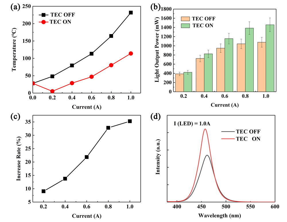
Figure 2: (a) Maximum temperature, (b) light output power, and (c) percentage light output power increase rate with TEC on. (d) Light intensity spectrum of LED at 1.0A injection.
It is also to be noted that the peak wavelength is longer with the TEC turned off. Such a red-shift is a well-known effect of increased junction temperature.
Simulations suggested that the LED without the TEC turned on could reach a temperature of 244°C at 1.0A injection. The calculations also suggested that with the TEC on this would be reduced to 150°C. Experimental temperature measurements with a thermal infrared imager gave 232°C with the TEC off, and 114°C with the cooler on.
https://doi.org/10.1109/TED.2021.3062314
The author Mike Cooke is a freelance technology journalist who has worked in the semiconductor and advanced technology sectors since 1997.


