


News: LEDs
12 August 2022
Color-tuning in V-groove InGaN μLEDs
Researcher Matthew Hartensveld of US-based firm Innovation Semiconductor Inc has demonstrated indium gallium nitride (InGaN) micro-LEDs capable of emitting tunable colors across the blue-to-red visible range from 425nm to 640nm [Optics Express, v30, p27314, 2022]. The devices are capable of covering the 1996 HP/Microsoft ‘standard’ red-green-blue (sRGB) color space for use on monitors, printers and the internet.
Although V-grooves have previously been found to enhance LED performance through improved carrier injection and minimizing charge recombination in threading dislocations, Hartensveld claims to be the first to use V-grooves to achieve color-tunable emission.
Hartensveld sees potential for the proposal to be deployed in full-color displays, offering high efficiency, environmental ruggedness, greater scaling, and higher brightness over competing technologies. Up to now, proposals for μLED displays tend to use different material families to achieve the different colors: aluminium indium gallium phosphide (AlInGaP) for red, and InGaN for blue and green. Such an approach is difficult to integrate at low cost. Further, the efficiency of AlInGaP μLEDs suffers from higher losses associated with sidewall leakage, relative to InGaN devices.
Rather than reducing defects, the devices used the resulting V-grooves nucleated at threading screw dislocations to give regions with different indium content and band structure (Figure 1), resulting in different emission wavelengths. Away from the V-groove green light was emitted, while deep in the grooves lower indium incorporation through the semi-polar facet gave blue light. At the same time, strain relaxation near the groove increased indium incorporation, resulting in red emission.
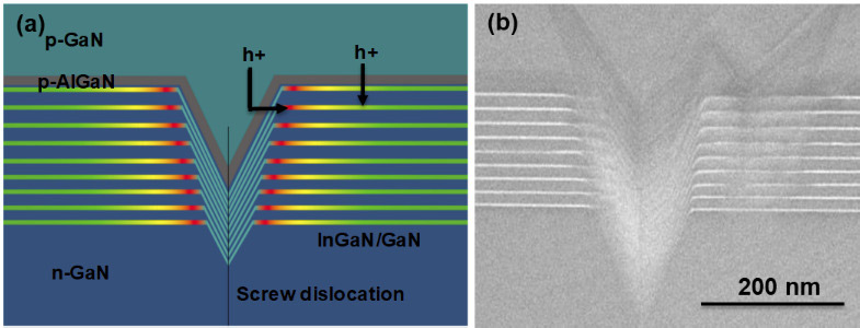
Figure 1: (a) Schematic of V-groove in color-tunable LEDs showing varying indium content and hole injection pathways, (b) transmission electron micrograph of grown structure showing V-groove.
Hartensveld comments: “Past works have sought to minimize V-groove inclusion, though a growing body of recent reports suggest the overall benefits to V-groove inclusion due to the ability to provide an energy barrier to minimize carrier recombination in threading dislocations and provide strain relief through a free surface depression.”
Metal-organic chemical vapor deposition (MOCVD) on sapphire was used to create green InGaN multiple quantum well (MQW) LED structures with V-groove densities greater than 4x10⁸/cm2. The stack included n-GaN beneath the MQW layer, and a p-AlGaN electron-blocking layer (EBL) and p-GaN above the MQW layer. The EBL uniformly coats the V-groove and planar regions, while the p-GaN fills in the groove, planarizing the surface.
Cathodoluminescence spectra showed blue (~425nm) and red (~619nm) emissions, along with the main green (~535nm) emission. The proportions depended on where the electron beam was focused – near or away from the V-grooves. There were also violet (~400nm) and yellow components (~565nm).
Hartensveld fabricated μLEDs of diameters ranging from 500μm down to 2μm. The mesa plasma etch was followed with hydroxyl-based wet etch treatment to repair sidewall damage. The n-type electrode consisted of titanium/aluminium/nickel/silver. The p-electrode was nickel.
The turn-on voltage of the devices was around 2V, and the ideality factor 2.5. Hartensveld believes that the ideality could be improved with optimized p-type metallization. The smaller devices naturally carried a smaller current for a given voltage, but a higher current density.
The color content of the electroluminescence (EL) emission depended on the current injection level, with red predominating at low current and blue at high current (Figure 2). “The applied current densities for the 35μm μLEDs have an approximate value of ~6x10⁻⁵ for red and ~8*10-2mA/μm2 for blue,” Hartensveld reports. He also proposes that differences in brightness due to the different current levels could be compensated through pulsed injection with different duty cycles.
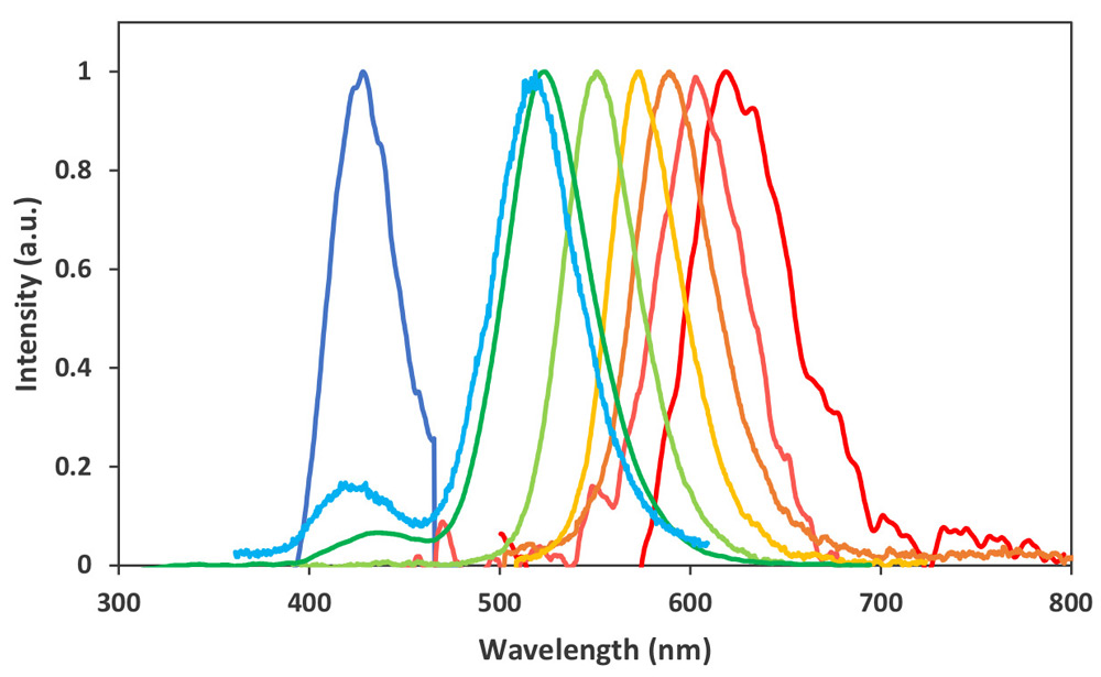
Figure 2: EL spectra plot of color-tunable μLEDs.
At low current, the hole injection is laterally across the V-groove to the nearby high-indium-content InGaN MQW region. At higher current, the injection becomes more vertical. These effects are attributed to lower charge polarization of the semi-polar facets of the V-groove resulting in a lower hole barrier presented by the EBL. As the applied bias increases, the quantum-confined Stark effect (QCSE) is reduced, enabling vertical injection, first away from and then in the V-grooves.
For a display, one needs the three primary colors: red, green, and blue. The devices with more than 200μm suffered from not being able to achieve sufficient current density for a pure blue, ending up with cyan from a mixing effect with green.
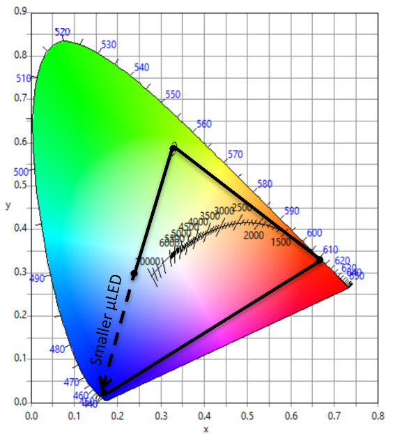
Figure 3: 1931 CIE color chart.
In smaller devices, good red and blue colors were achieved, but the green corner of the 1931 CIE triangle was somewhat away from the desired edge of the chart (Figure 3). However, the triangle does just cover the sRGB space. Hartensveld believes that the green output could be optimized for greater coverage in future. He also points out that the red performance is comparable to that obtained by europium (Eu) doping.
The largest 500μm μLEDs were subjected to wall-plug efficiency (WPE) characterization with a green emission peak at 3%. At the lower initial turn-on currents needed for red emission, the WPE was ~0.6%. Higher currents for blue suffered from efficiency droop to ~1.15% WPE. Hartensveld compares these values to the external quantum efficiency (EQE) reports of 0.2% for red LEDs on porous GaN, and 0.56% for strain-engineered amber LEDs.
Hartensveld has hopes of maximizing the WPE through suitable packaging, along with other optimizations, given that the present record-efficiency red InGaN LED structure uses V-grooves in its design.
The author Mike Cooke is a freelance technology journalist who has worked in the semiconductor and advanced technology sectors since 1997.


