


News: LEDs
15 February 2024
Probing InGaN RGB micro-LEDs on silicon
Xiamen University and Latticepower Co Ltd in China report on the characteristics of micron-scale light-emitting diodes (LEDs) fabricated from aluminium indium gallium nitride (AlInGaN) structures grown on silicon (Si) with a view to their use in displays, particular for virtual-reality and augmented-reality (VR/AR) systems [Xi Zheng et al, Appl. Phys. Lett., v124, p051103, 2024].
The team comments: “Few investigations have been carried out on the chromatic characteristics of the InGaN-based red, green and blue (RGB) micro-LEDs system grown on silicon substrates, which can contribute to a better understanding of the designs of the driver, back-plane integration, and heat dissipation.”
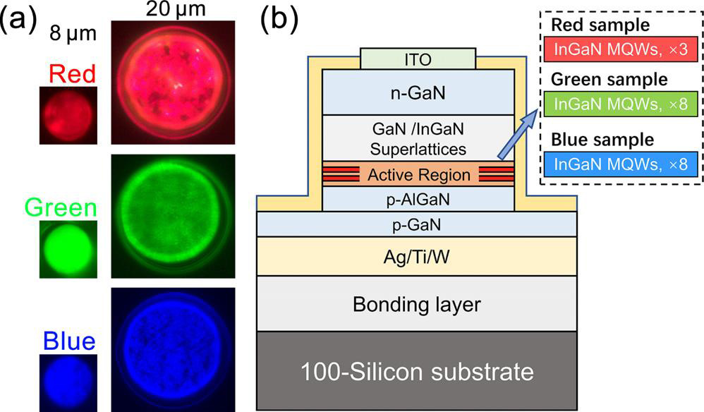
Figure 1: (a) Electroluminescence emission images (at 1A/cm2) of red, green and blue micro-LEDs with diameters of 8μm and 20μm, respectively. (b) Schematic cross-section for red/green/blue micro-LEDs.
The researchers used metal-organic chemicalvapor deposition (MOCVD) on 4-inch (111)silicon to prepare the materials for the respective micro-LEDs (Figure1).
LEDs with 8μm and 20μm diameters were fabricated: The first step was to deposit silver/titanium/tungsten (Ag/Ti/W) on the p-GaN contactlayer, using electron-beam evaporation. The material was flipped and bonded onto a (100)Si substrate, and the (111) growthsubstrate was removed. The n-contact electrode consisted of indiumtinoxide (ITO). Silicondioxide (SiO2) was used for passivation.
While the green and blue multiplequantumwell (MQW) active regions used 8-period structures with InGaNwells and GaN barriers, the red device had only three wells of InGaN separated by AlN/AlGaN/GaN hybrid barrierlayers. The aim was to reduce lattice mismatch, relieving the strain of the high-indium-content InGaN epitaxial layers.
The longer-wavelength red-emitting devices suffered from reduced performance. Current-voltage measurements showed an ideality factor (n,‘ideal’=1) increasing with wavelength: 1.79, 2.60 and 3.08 for the blue, green and red micro-LEDs, respectively. The team comments: “When the factor n is larger than 2, the inferior carrierinjection efficiency may originate from the severe defect-assisted non-ideal carrier transport, including trap-assisted tunneling, carrier leakage etc, the larger n of the red micro-LEDs can be attributed to the non-radiative centers induced by defects.”
Table 1: Micro-LED performance, 8μm diameter.
Color |
EQEmax |
Wavelength |
FWHM |
EQE droop @100A/cm2 |
| Blue | 6.1% (@16A/cm2) | 467nm | 22nm | 9.6% |
| Green | 3.8% (10A/cm2) | 545nm | 35nm | 26.6% |
| Red | 0.23% (0.265A/cm2) | 689nm | 70nm | 55.3% |
Study of the light-emission of the 8μm- (Tableb) and 20μm-diameter (Tablec) LEDs showed reduced external quantumefficiency (EQEmax) maximum performance for the longer wavelengths, and smaller diameter. Also, the full-width at half-maximum (FWHM) of the emission spectrum was broader for the green and red devices.
The reduced performance of the smaller devices is attributed to the increased importance of sidewall damage leading to greater non-radiative recombination of electron and hole chargecarriers.
Table 2: Micro-LED performance, 20μm diameter.
Color |
EQEmax |
Centroid wavelength |
FWHM |
EQE droop @100A/cm2 |
| Blue | 8.2% (2.65A/cm2) | 467nm | 23nm | 18.6% |
| Green | 5.1% (5.3A/cm2) | 544nm | 36nm | 36.2% |
| Red | 0.62% (0.1A/cm2) | 688nm | 72nm | 59.5% |
Also, stronger quantum-confined Starkeffect (QCSE) and higher defectdensities in the higher-indium-content MQWs needed for longerwavelengths results in a more severe droop in EQE at higher currentinjection from the maximum value. QCSE refers to the presence of strong electricfields in strained semiconductor structures from the different charge polarizations of the chemical bonds in the various layers.
The reduced droop effect in the smaller devices was attributed to “better currentcrowding and heat dissipation in a smaller mesa”.
The devices also suffered from a blue-shift at higher currentinjection due to screening of built-in QCSE electricfield and band-filling effects effectively widening the bandgap.
The researchers calculated the the color performance of the the devices in combination and separately (Figure2). The researchers used comparison standards from the ITU-Recommendation BT.2020 (Rec.2020) and National Television Systems Committee (NTSC). Area ratios compare the colortriangle areas on the chromaticity diagram of a notional display using the RGB LEDs relative to the standard (hence it can exceed 100%). The coverage ratio only includes the display trianglearea inside the standard relative to the standard (and hence must be less than 100%).
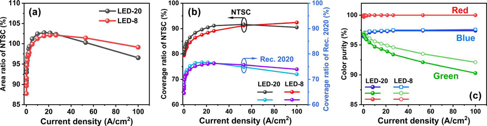
Figure 2: (a) Current density dependence of area ratio of NTSC for mixed RGB micro-LED systems. (b)Coverage ratio of NTSC and Rec.2020 under different currentdensities. (c)Colorpurity versus currentdensity for separate RGB micro-LEDs with dimensions of 8μm and 20μm.
In terms of color purity of the RGB devices, the green LED was seen to suffer from a severe decline as the currentinjection increased. The team comments: “Since the color gamut of the RGB mixedsystem is more sensitive to the chromaticity coordinate of the green self-emitting unit, the lower colorpurity of the 20μm green micro-LED can result in the decrease in the area ratio and the coverage ratio of the standard colorgamut of the RGB mixed micro-LED systems.”
The researchers also studied the thermal stability of the devices between 290K and 350K. The shift for the 20μm LEDs was larger than for 8μm. The researchers say that this suggests that “the micro-LEDs with a shrunken mesa dimension can exhibit superior chromatic stability with temperature, which can be explained by the better heatdissipation and higher colorpurity of the 8μm micro-LEDs.”
The author Mike Cooke is a freelance technology journalist who has worked in the semiconductor and advanced technology sectors since 1997.